Installation
- The unit must be installed in the passenger compartment.
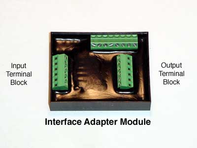
- Cut the six coil drive wires at a convenient point. Install the adapter terminal block as shown, between the cut ends.
- Connect the SafeGuard to the adapter as shown, using the six conductor cable supplied in the kit.
- Connect the J&S Red wire to a switched power source. Note that 12v must be present during cranking and running.
- Connect the J&S Black wire to chassis ground.
- Connect the "clear" wire of the J&S knock sensor cable to the factory knock signal wire. Tap the signal near the ECU, to avoid cutting though the shield on the factory knock sensor cable.
- At a convenient point, cut the 1/8" nylon tubing that feeds the vacuum/boost gauge. Install the supplied brass compression tee fitting in line.
- Connect one end of the supplied vacuum hose to the brass tee, and route the hose to the back end of the J&S unit. For now, plug the hose.
Initial Test
- At Key On, the unit performs a self check. The Status LED will flash ten times over a two second period. If you have one of our optional bargraph displays connected to the monitor jack, the display will count up and back down.
- Turn the key off, then back on again, and ensure that the Status LED flashes. Note that if the J&S Red wire is connected to the battery, the self test will not repeat (and the battery will discharge).
- The self test is bypassed when the engine is cranked.
- After double checking your work, crank the engine. During cranking, the Status LED on the front panel should pulse with each spark event. If the pulses seem irregular, stop and check your work again. The pulses should be evenly spaced.
- Above 500 RPM, the Status LED goes out, and above 1750 RPM, the function of the LED changes to indicate knock retard. The brightness will vary in proportion to the amount of knock retard.
- The unit ignores the knock sensor until the following conditions are met:
- Engine exceeds 1750 RPM
- Vacuum drops below 5 inches
- To test the knock retard function, temporarily:
- Set mode switches 1 and 2 on the front panel up. This sets the unit to 20° knock retard range, and retard all cylinders, making it easier to tell that the unit is retarding.
- Leave the vacuum/pressure port on the back of the unit open. This forces the onboard MAP sensor to 0 psi.
- Run the engine at about 2000 RPM
- Have an assistant tap rapidly on or near the knock sensor.
- You should hear the engine slow down, as it retards. Verify this with a timing light. Check that the Status LED glows.
Boost Retard
- If you wish to preset and verify the amount of boost retard, temporarily connect a MityVac or equivalent hand operated pump to the brass fitting on the back of the unit.
- Set the Boost Retard "Start" knob fully CCW, to ensure that boost retard will start at 0psi.
- Set the "Rate" knob for the desired amount of retard per psi. Fully CCW is 0, mid range is 1° per psi, fully CW is 2° per psi. Proportional amounts in between.
- Start the engine.
- Apply the desired amount of pressure to the unit.
- With a timing light, verify the amount of boost retard. Tune the amount, using the "Rate" knob.
- Use the Boost Retard "Start" knob to change at what psi boost retard begins. If set to mid-range, the boost retard will not begin until 5 psi. Fully CW, and boost retard will not start until 10 psi.
- Note that the maximum amount of boost retard is 20°, and is in addition to any amount of knock retard.
- The onboard MAP sensor reads up to 15 psi.
RPM Retard
- To offset the aggressve factory timing curve at high RPM, the unit has an RPM based retard curve. Mode switches 3 and 4 allow you to select two, four, six, or eight degrees of RPM retard. See the table below:
- S3 S4 Retard
- 1 1 = 8°
- 1 0 = 6° (Note: 1 = UP)
- 0 1 = 4°
- 0 0 = 2°
-
- Note: units may also be ordered with 0, 2, 4, or 6 degrees RPM retard
-
- Assuming boost exceeds 4 psi, the retard begins at 5250 RPM, and increases linearly with RPM, and is all in by 6250.
- If boost is less than 2 psi, there is no RPM retard. Between 2 psi and 4 psi, proportional amounts
Switched Retard
- An additional amount of retard is added when the "Aux" pin (Pin 2 of the harness connector) is switched to 12v. Mode switch S5 UP adds 4°, DOWN adds 2°.
- The "Aux" wire may be connected to a nitrous solenoid, or wire it to a "Low Octane" switch.
Sensitivity Adjust
- The sensitivity must be set on a road test. For safety, take along an assistant.
- Piston engines can be noisy at low loads, due to piston slap. For this reason, the unit ignores the knock sensor until vacuum drops below 5 inches.
- Bring the vehicle to freeway cruising speed.
- Temporarily disconnect the vacuum hose from the rear of the unit. Plug the hose.
- Start with the Sensitivity knob fully CCW, and turn it CW slowly, until the unit just starts to detect engine noise, then back it off slightly. The engine should not be in boost at this time.
- Reconnect the vacuum/boost hose.
Tuning
- Maximum power will be achieved at the threshold of knock. The Status LED can be used as a tuning aid.
- Adjust the Boost Retard "Start" and "Rate" knobs for minimal knock retard activity. At high RPM, use mode switches S3 and S4 to select an additional amount of RPM based retard.
- The Status LED can be used to assist in tuning the fuel curve. Check the A/F ratio when you see knock retard activity.