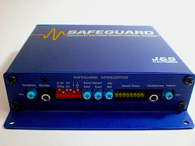
Eight Channel Interceptor
Designed for coil on plug or waste spark ignition. Drives ignition modules or coils with internal igniters, also known as "Smart Coils".
New features include a headphone amplifier to listen for knock, and "knock-finder" LED's to show which cylinders are knocking. Boost retard, nitrous retard, and individual cylinder knock retard are also included.
Progressive nitrous retard capability (added 11/15/09). For those using a progressive nitrous controller with a 0-5v output, the unit will retard proportionately.
Example Installation Diagram
(Toyota coils shown)
Toyota MR2 Spyder Installation Example:
1) The unit controls timing by intercepting the coil drive signals, and delaying them if necessary. These signals leave the ECU on connector D. Cut them at a convenient point. The service manual refers to these signals IGT1,1GT2, IGT3, and IGT4. Note that they go to pin 2 of each coil connector. For reference, pin 1 on each coil is Red/Black (12 volts).
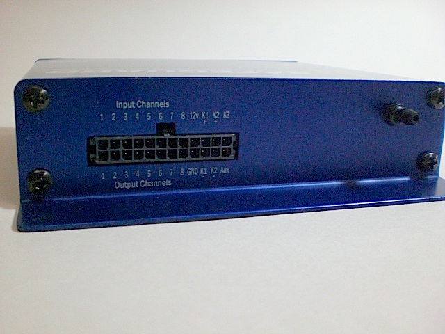
2) Connect the ECU ends of the cut wires to the J&S inputs. For the knock-finder LED’s to indicate the correct cylinder, the unit must be connected as follows: Cyl 1 to Input 1, Cyl 2 to Input 2, Cyl 3 to Input 3, and Cyl4 to Input 4.
The coil ends of the cut wires will connect to the J&S outputs in the same order, but leave them disconnected for now.
3) Connect the J&S Red wire to switched 12 volts. Pin 1 of any coil is ideal, as it ensures the unit is powered during cranking as well as when running. Ground the J&S Black wire to the chassis.
4) Use a vampire tap to splice the “Clear” wire in the J&S Gray knock sensor cable to the factory knock sensor wire. You can do this at the ECU.
5) If you are running nitrous, splice the J&S Red/Grn wire to the nitrous solenoid. The unit will then retard at nitrous turn on. The amount is adjustable, from 0 to 10°. You could also connect the wire to a toggle switch to 12v and activate it in case of low octane.
6) At power-up, the unit performs a self check. The Status LED above the monitor jack will flash ten times over a two second period. At the same time, it will exercise a knock retard gauge if pluged into the monitor connector. The test will be aborted when the key is moved to the start position.
7) The Status LED pulses during cranking and idle. Above 1750 RPM, the function of the LED changes to show the amount of knock retard. With no knock retard, the LED will be off. When knock retard occurs, the LED brightness will increase in proportion to the amount of knock retard.
Before proceeding further, verify the Status LED (not the gauge) pulses during cranking, indicating the unit is detecting ignition triggers. If the Staus LED flashes during cranking, connect the J&S outputs to the coils as indicated in step 2 above.
To prevent damage to the coils, do not connect them to the unit until it detects triggers during cranking.
To troubleshoot, verify that 12v is present on the J&S Red wire during cranking. Some accessories are turned off during cranking. Also, verify the ground connection.
Next, the input “pull select” resistors may not be configured correctly. Inside the unit, there is a group of eight switches, located directly behind the knock-finder LED’s. These are three position switches. For most applications, including Toyota MR2 Spyder, Honda S2000, Nissan, etc. the switches should be pushed towards the LED’s, configuring “Pull Down” resistors on the inputs. All units are shipped in this configuration.
If your application requires “Pull Up” resistors (for example, Mitsubishi 3000GT), push the switches to the other side. For no pull resistors, set the switches to the center position.
Connect the coils to the unit after you have verified the Status LED flashes during cranking.
8) Configure mode switches as described on sheet 1. Note that for most aplications S5 should be down, configuring the unit to trigger on the falling edge of the ignition pulse. If you have a standalone and are using an MSD DIS ignition, note that MSD triggers on the rising edge, so you will need to set the standalone for rising edge output, and J&S for rising edge input (S5 up).
9) Once you have the car running normally on the J&S unit, you are ready to test the knock sensor. The unit will not detect and retard from knock unless the following conditions are met:
a) RPM must be above 1750 RPM
b) Vacuum drops below five inches.
Note that boost retard and nitrous retard work at any RPM.
10) Temporarily unplug and cap off the source of manifold vacuum. This forces the on board MAP sensor to 0 psi, to enable knock retard. Also, temporarily set mode switches 1 and 2 up.
11) Set the sensitivity control to mid-range, and hold the RPM to at least 2000. You should be able to hear the engine slow down as you tap rapidly on the knock sensor with a screwdriver. You can also see the timing retard with your timing light, and the Monitor LED on the front panel will glow dimly, increasing in brightness with increasing knock retard. If you have the J&S Knock/Retard Bargraph display, you can also see the amount of retard.
12) Once you have verified that the unit retards with knock, set mode select switch # 2 down. This returns the unit to the individual cylinder retard mode. Do not reconnect the source of manifold pressure until after the initial test drive. If you know the timing in your tune is fairly close, you may set mode switch #1 down. The limits the amount of knock retard to 10°. Up is 20° max.
13) Sensitivity Adjust: Now you are ready for your test drive. A common mistake is to set the sensitivity control to maximum. This will usually cause the unit to over-retard due to engine noise. We recommend setting it to mid-range and getting the car up to highway cruising speed. To ensure that the unit is armed,temporarily disconnect the vacuum hose from the rear of the unit, forcing the MAP to see 0 psi. Increase the sensitivity until the unit just starts to retard due to engine noise. Some engines don’t make much noise, so you will need to use your judgement. This is easiest to do if you have purchased one of our knock retard monitors. If you don't have a monitor, the Monitor LED on the front panel will glow dimly, increasing in brightness with increasing knock retard. In any case, give the unit only as much sensitivity as it takes to make the ping go away.
14) Observe the monitor LED when setting the boost (vacuum) retard. Adjust the boost retard so that knock retard is kept at a minimum.
15) Boost Retard Start: The Start knob sets at what boost pressure the boost retard begins. Fully CCW, the boost retard starts at zero psi. Fully CW, and boost retard starts at 10 psi.
16) Boost Retard Rate: The boost retard rate is adjustable, from zero (fully CCW), to two degrees per psi (fully CW).
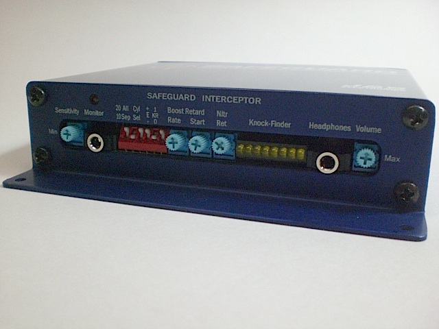
17) The knock-finder LED’s indicate which cylinders are being retarded. This is most useful if you have a standalone that allows you to trim timing or fuel in each cylinder. Note these LED’s will also light if boost retard or nitrous retard is activated.
18) The headphone jack on the right side of the front panel can be used to listen for knock, if desired, to aid in tuning.
19) Mode switch #6 is the “Detector/Controller” switch. With S6 up, the unit functions as a closed loop knock conroller. S6 down disables knock retard, but the bargraph voltage is still active for data logging, and is available at pin "K3" of the main harness at the rear of the unit. The range is 0 to 1.3v full scale.