
 |
1) Connect the unit to a source of manifold vacuum/pressure. The supplied brass “tee” compression fitting may be
used to tap into your boost gauge.
2) The Boost Retard “Start” knob is used to adjust the onset of boost retard. Measure the voltage at the “TP” (test point). If you want the boost retard to start at 3 psi, turn the “Start” knob until the test point reads 3 volts. Fully CCW and the boost retard will begin at 0 psi. Fully CW, and the boost retard will begin at 10 psi.
3) The “Rate” knob sets the amount of retard per psi of boost. Fully CCW, no boost retard. Fully CW, the rate is 2° per psi, up to a total of 20° max boost retard.
4) Knock retard is not enabled until the vacuum drops below 5 inches, and RPM exceeds 1250.
5) The LED above the monitor jack pulses during cranking and idle. Above 1250 RPM, the function of the LED changes to show the amount of knock retard. With no knock retard, the LED will be off. When knock retard occurs, the LED brightness will be in proportion to the amount of knock retard.
6) Observe the monitor LED when setting the boost retard. Set the boost retard so that knock retard is kept at a minimum.
7) If the unit is connected to the TPS wire, the unit will pull the TPS signal to 5v at 0 psi. This should kick the ECU out of closed loop operation.
8) At power-up, the unit performs a self check. The monitor LED will flash ten times over a two second period. At the same time, it will exercise a knock retard monitor if pluged into the monitor connector. The test will be aborted when the key is moved to the start position.
9) The MAP Limiter LED will turn on when the input voltage exceeds the set point, and is in the clamping mode.
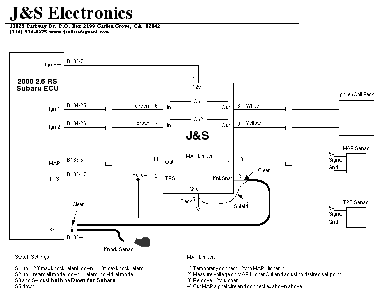
10) Mode Switch 1 sets the unit to 10° or 20° knock control range. Up is 20°.
11) Mode Switch 2 sets the unit to retard all or retard individual cylinder mode. Up is retard all mode.
12) Switches 3 and 4 are used to select the application:
3 4
up up Honda
up dn Toyota
dn up 1.6/1.8 Miata
dn dn Subaru/Eclipse/all Miata
13) Mode switch 5 turns the AFC on and off. Down is off. LEAVE SWITCH 5 DOWN. At present, the AFC is not programmed. If the switch is up, the onboard MAP sensor will be fed to the MAP Limiter. The output will vary from 0 to 5v as the manifold pressure goes from vacuum to 15 psi. The MAP Limiter set point will still be in effect.
14) In the future, the AFC voltage will be calibrated for various injector sizes. Units may be returned for programming, at a nominal charge.
15) Honda VTEC turn on is sensed to squelch turn on noise that could cause the knock sensor to activate.