1) The SafeGuard control unit must be mounted inside the passenger compartment. We recommend hiding it under the carpet on the passenger side.
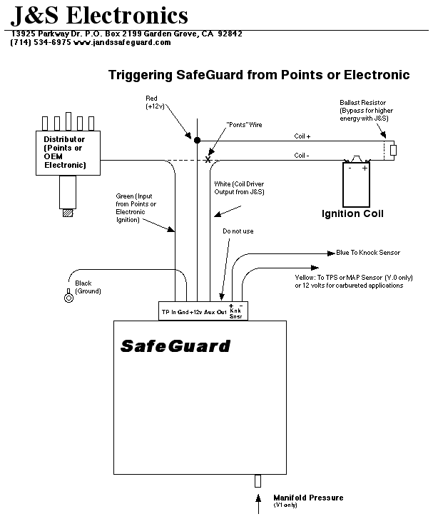
2) The supplied harness is ten feet in length. This allows you to connect either in the engine compartment or directly to the ECU. If you choose to install in the engine bay, feed all the wires through the firewall. Make sure you leave enough wire inside the car so you can adjust the unit on your test drive.
3) Cut off about two feet of the large diameter flex-loom and slide it over the wires inside the car. This will protect them and keep them from getting tangled up in the pedals. Tie-wrap the loom up under the dash.
4) In the engine compartment, slide the remaining loom over the wires and route them along the firewall, then out to the ignition coil.
5) Cut the coil negative (ignition) wire at a convenient point. Crimp a female terminal onto the ECU end, and a male terminal on the coil end of the ignition wire.
6) The J&S Green wire will connect to the “points” or distributor end of the cut ignition wire and the J&S White wire will connect to the coil side of the cut wire. Dress the J&S wires, cut them to proper length, and crimp on the matching connectors.
7) Ground the J&S Black wire.
8) Using the wire splice provided, connect the J&S Red wire to the coil positive wire.
9) Install the sensor into the block, and torque to about 15ft. lbs. Route the Blue knock sensor wire, and cut to length. Install the mating connector, and connect to the sensor.
10) Version 0 units require the J&S Yellow wire to be connected to the TPS or MAP sensor wire. The “Rate” knob is used to set at what TPS or MAP voltage the unit is armed to detect knock. With the knob set to mid range, the unit is armed at 2.5 volts. This is half throttle on the TPS sensor. Turning the knob counter-clockwise will arm the unit at lower TPS voltages. If this is a carbureted application, and there is no TPS or MAP sensor, connect the Yellow wire to 12 volts. If the wire is left unhooked, the unit will never arm or detect knock.
11) The Ultra V1 requires a source of manifold vacuum. With switch 6 up, the unit is not armed to detect knock until the vacuum is less than five inches. Switch 6 down, the unit is not armed to detect knock until the vacuum goes below 15 in. The brass tee fittings included in the kit let you tap in to the 1/8” teflon tubing used on most boost gauges.
12) Switch Settings Set the Mode Select switches at the front of the unit as follows:
Switch 1 is the 10°/20° range switch. Down is 10° max retard, up is 20° max retard. For now, leave it up.
Switch 2 is the retard all/retard separate switch. Up is retard all. Temporarily set switch 2 up.
Switches 3 and 4 select the number of cylinders. Use the following table:
S3 S4
1 1 = 8 cyl
0 1 = 6 cyl
1 0 = 5 cyl (NOTE: 0 = down)
0 0 = 4 cyl
Switch 5 must be up. Switch 5 up is rising edge trigger.
Switch 6 is the Forced Induction/Naturally Aspirated mode switch (not used on V.0). Up is forced induction.
13) Start the car. The Status LED should blink during cranking. If it doesn’t blink, the unit is not receiving or processing triggers. If the car runs normally, skip to step 16. If the engine doesn’t start, leave the key on, and use a voltmeter to make sure that 12 volts is getting to the connector on the Black and Red wires. Make sure there is at least 8 volts during cranking.
14) After verifying power and ground, turn off the key, and unplug the unit from the harness. Form a paper clip to fit in the harness connector to jumper the Green and White wires. Make another starting attempt. Do not touch the paper clip while the engine is running. High voltages are present from the ignition coil. If the engine still doesn't start, you will need to check the connections on the Green and White wires at the coil.
15) Once the car runs with the paper clip installed, you must still verify that Green goes to the TFI module and White goes to the coil. Note that if these are reversed, the car would still run with the jumper installed.
16) Once you have the car running normally on the J&S unit, you are ready to test the knock sensor. The unit will not detect knock unless the following conditions are met:
1) RPM must be above 1250 RPM
2) V.0 units: TPS voltage exceeds the user defined threshold
3) V.1 units: Vacuum drops below five inches (S6 up) or fifteen inches (S6 down).
17) On Version 0 units, temporarily set the “Rate” knob fully CCW. This sets the internal TPS switch to arm at 0 volts. Make sure that the Yellow wire is connected to the either the TPS or the MAP sensor. If a carbureted application, connect Yellow to 12 volts, and set the “Rate” knob to mid range.
18) If you have a Version 1 unit, temporarily unplug and cap off the source of manifold vacuum. This forces the on board MAP sensor to 0 psi.
19) Set the sensitivity control to mid-range, and hold the RPM to at least 1500. The unit is prohibited from retarding if the RPM is less than 1250 RPM. You should be able to hear the engine slow down as you tap rapidly on the knock sensor with a screwdriver. You can also see the timing retard with your timing light, and the Monitor LED on the front panel will glow dimly, increasing in brightness with increasing knock retard. If you have the J&S Knock/Retard Bargraph display, you can also see the amount of retard.
20) Once you have verified that the unit will retard, set mode select switch #2 down. This returns the unit to the individual cylinder retard mode. On Version 0 units, set the “Rate” knob so that the unit will arm at the desired TPS voltage. On Version 1 units, reconnect the source of manifold pressure.
21) Sensitivity Adjust: Now you are ready for your test drive. A common mistake is to set the sensitivity control to maximum. This will usually cause the unit to over-retard due to engine noise. We recommend setting it to mid-range and getting the car up to highway cruising speed. For Version 0 units, set the “Rate” knob to about 10:00 o’clock. This will set the TPS threshold to about 1.5 volts. For Version 1 units, make sure there is less than ten inches of vacuum. Once the unit is "armed", increase the sensitivity until the unit just starts to retard due to engine noise. This is easiest to do if you have purchased one of our knock retard monitors. If you don't have a monitor, the Monitor LED on the front panel will glow dimly, increasing in brightness with increasing knock retard. In any case, give the unit only as much sensitivity as it takes to make the ping go away.
22) Boost Retard: On Version 1 units, Switch 6 up calibrates the MAP sensor for Boost Retard. The Start knob sets at what boost pressure the boost retard begins. Fully CCW, the boost retard starts at zero psi. The TP (Test Point) is calibrated in volts per psi. Zero volts equals zero psi. If you set the voltage to five volts, the boost retard will not start until five psi.
23) Vacuum Advance: On Version 1 units, Switch 6 down calibrates the MAP sensor for Vacuum Advance. The start knob sets at what vacuum the retard will begin. Fully CCW, the retard starts as the vacuum goes below ten inches, which is equivalent to minus 5 psi. If you want the unit to start retarding as the vacuum goes below ten inches, set the voltage on the test point to 0 volts. If you don’t want any vacuum advance, set the knob so the test point reads at least 5.0 volts. Or just turn the Rate knob fully CCW.
24) Start knob: On V.1 units, note the manifold pressure (or vacuum) when knock retard activates. Since we want to pre-empt knock, start the retard a little early. Connect your voltmeter to the TP and Ground. Adjust the knob until the voltage corresponds to the manifold pressure (or vacuum) level you want the retard to begin.
25) On version 0 units, the “Rate” knob is used to set the TPS arming voltage. With the knob fully CW, the unit will not arm until the TPS reaches 5 volts. With the knob at midrange, the unit will arm at 2.5 volts. As you turn the knob CCW, the unit will arm at lower TPS voltages.
26) Boost Retard Rate: On Version 1 units, the boost retard rate is adjustable, from zero degrees fully CCW, to two degrees per psi fully CW. When switch 6 is set down for naturally aspirated mode, the retard rate is adjustable from 0 to 1° per inch of vacuum, 10° maximum.
27) Bargraph Test When the key is first turned on, the Monitor LED on the front panel should blink for two seconds. If you have the optional bargraph display, it will count up and back over a two second period. The test can be aborted by moving the key to start. Some piggy-back computers, such as the PMS computer, put out a start pulse at power up which aborts the test automatically. If you have one of these, you will see the first LED on the bargraph blink briefly when the key is turned on.
28) Status LED The Status LED pulses each time the coil fires. During cranking, the pulses are slow enough to see.
29) Monitor LED The Monitor LED glows dimly during knock retard, and gets brighter with increasing knock retard. It does not show boost retard.