The control system retards only the knocking cylinders, maximizing power while protecting the engine.
The system also features boost retard and nitrous or switched retard.
The boost retard section includes Start and Rate controls, allowing you to tailor the retard curve to your needs.
Switched retard could be enabled by a nitrous switch or a manual toggle switch, in case you fill up with low octane fuel.
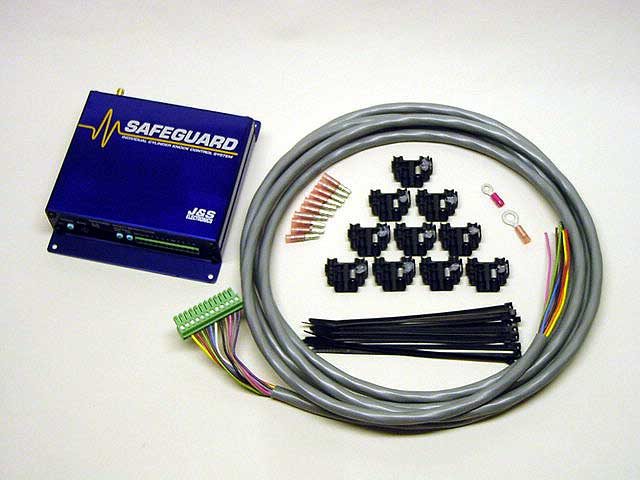
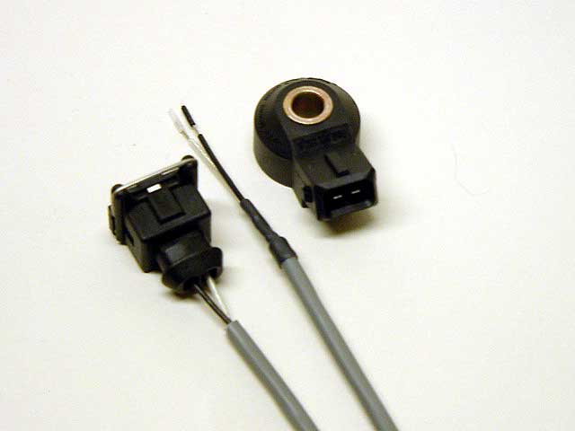
If factory knock sensor is not present, order our Bosch sensor kit, shown below.
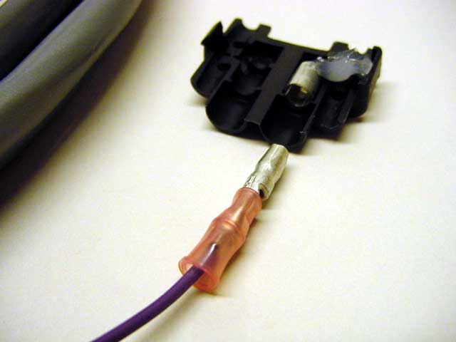
The connector body is a 3M 901 wire splice, which is clamped to the coil negative wire.
Note that a dab of silicone dielectric grease (included) has been applied to the splice, to prevent corrosion of the factory harness.
A bullet connector is then crimped to the J&S control wire, which plugs into the connector body.
2) Locate the eight coil drive signals on the EECV computer. Using Vampire taps provided in the kit, splice the J&S Control wires to the coil drive signals. Firing order is not important. Any J&S control channel can go to any coil drive signal.
NOTE: If you have the Knock-Finder option, wire the coils in order, 1-8. Then LED 1 will relate to cylinder 1, LED 2 will relate to cylinder 2, etc. This will make it easy to tell which cylinders are knocking.
NOTE: The Blue wire is a spare, or may be used for some “one wire” knock sensors.
3) Connect the Red wire to switched 12 volts. Coil positive is ideal, since 12v is present during Cranking as well as Run.
4) Connect the Black wire to a good chassis ground (not sheet metal).
5) Install the Bosch knock sensor on the engine block. Run the gray knock sensor cable through the firewall. Crimp the connector pins onto the black and clear wires, then insert pins into the rear of the connector body. Polarity is not important plug the connector into the knock sensor.
6) Connect the unit to a source of manifold vacuum/pressure. The supplied brass “tee” compression fitting may be used to tap into the 1/8” nylon tube going to your boost gauge.
7) If you are using nitrous oxide, connect the J&S “Aux” wire to the nitrous switch. When you hit the nitrous switch, the unit will retard either 2° (S5 down) or 4° (S5 up). You could also wire pin 2 to a toggle switch, and use it to retard 2° or 4° when you fill up with low octane fuel.
8) At power-up, the unit performs a self check. The monitor LED will flash ten times over a two second period. At the same time, it will exercise the optional knock retard bargraph monitor if pluged into the monitor connector. The test will be aborted when the key is moved to the start position.
9) The LED above the monitor jack pulses during cranking and idle. Above 980 RPM, the function of the LED changes to show the amount of knock retard. With no knock retard, the LED will be off. When knock retard occurs, the LED brightness will increase in proportion to the amount of knock retard.
10) Once you have the engine running on the J&S unit, you are ready to test the knock sensor. The unit will not detect knock unless the following conditions are met:
a) RPM must be above 1750 RPM
b) Vacuum drops below five inches.
11) Temporarily unplug and cap off the source of manifold vacuum. This forces the on board MAP sensor to 0 psi. Also, temporarily set mode switches 1 and 2 up, making it easier to tell if the unit is retarding.
12) Set the sensitivity control to max, and hold the RPM to at least 2000. You should be able to hear the engine slow down as you tap rapidly on the knock sensor with a screwdriver. You can also see the timing retard with your timing light, and the Monitor LED on the front panel will glow dimly, increasing in brightness with increasing knock retard. If you have the J&S Knock/Retard Bargraph display, you can also see the amount of retard.
13) Once you have verified that the unit retards with knock, set mode select switches 1 and 2 down. This returns the unit to the individual cylinder retard mode, and 10° range. Reconnect the source of manifold pressure. Set the Sensitivity control to mid range.
14) Sensitivity Adjust: Now you are ready for your test drive. A common mistake is to set the sensitivity control to maximum. This will usually cause the unit to over-retard due to engine noise. We recommend setting it to mid-range and getting the car up to highway cruising speed. To ensure that the unit is armed, find a slight hill, and run at 0 psi. This should be a low enough boost setting to avoid knock, but enough to arm the unit. Increase the sensitivity until the unit just starts to retard due to engine noise. This is easiest to do if you have purchased one of our knock retard monitors. If you don't have a monitor, the Monitor LED on the front panel will glow dimly, increasing in brightness with increasing knock retard. In any case, give the unit only as much sensitivity as it takes to make the ping go away.
15) Observe the monitor LED when setting the boost retard. Adjust the boost retard so that knock retard is kept at a minimum.
16) Boost Retard Start: The Start knob sets at what boost pressure the boost retard begins. Fully CCW, the boost retard starts at zero psi. Fully CW, and boost retard starts at 10 psi.
17) Boost Retard Rate: The boost retard rate is adjustable, from zero (fully CCW), to two degrees per psi (fully CW).
The engine is 2.0L with 14:1 compression ratio. The class requires a 24mm inlet restrictor, limiting power at high RPM.
ECU is a MoTeC M400.
The baseline was determined on the dyno using knock sensing headphones, and is retarded two degrees for safety.
The SafeGuard was then installed, and timing progressively bumped.
The final run was with higher octane (spec) fuel.
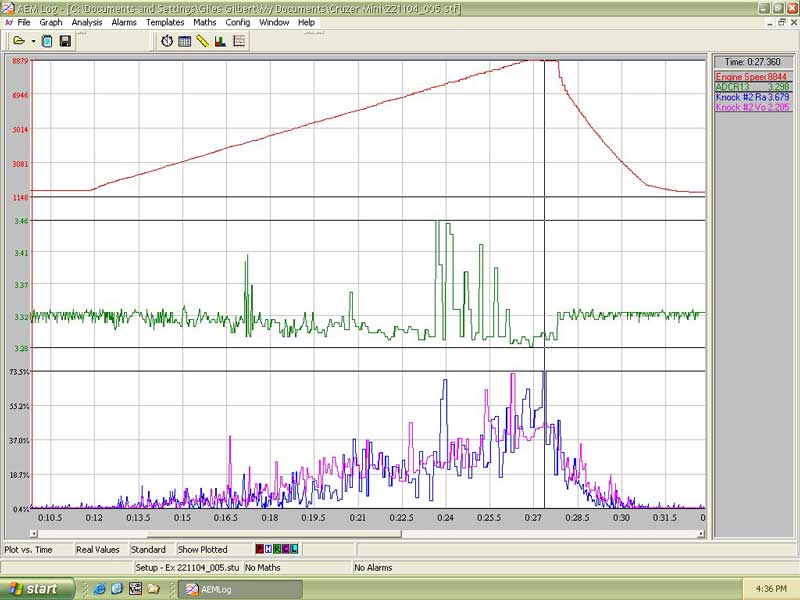
The customer reports that the dyno operator could hear nothing more than occasional trace knock, yet the SafeGuard was controlling timing on the cylinders that were inaudibly knocking, allowing the other cylinders to make more power.
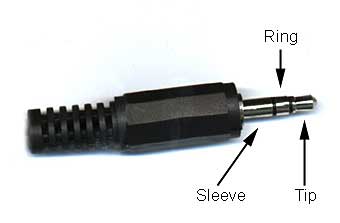
If desired, the signal that drives the bargraph could be data logged. You will need a 3.5 mm STEREO plug, available at Radio Shack.
The range of the signal is 0 to 1.3v.
Tip supplies 12v to power the gauge
Retard signal is on the Ring
Sleeve is ground.
The vehicle is a turbocharged Honda S2000
The Brown trace is RPM.
The Green trace is the J&S bargraph voltage, logged on a spare channel of the AEM.
The Blue and Violet traces are the internal AEM knock logs, showing raw and filtered knock signal.